Overview
The EM34-3 is a conductivity meter that uses an electromagnetic inductive technique that measures the soil’s apparent conductivity. The EM34’s large transducer coil produces a magnetic field causing a voltage that interacts with the subsurface below to create a secondary magnetic field. This secondary magnetic field’s strength varies depending on the properties of the subsurface and measured by the EM34’s receiver coil.
Given the ability to use three large intercoil spacings, 10, 20, and 40 meters, the EM34-3 is able to provide a depth of exploration up to 60 meters. The EM34-3 can be used in the vertical or dipole mode and is very useful for finding geologic anomalies such as fractured and faulted bedrock. For this reason, it is often used for groundwater exploration to find potable water or locate deeper groundwater contaminant plumes.
EM34-3 Configurations and Considerations
The EM34-3 is the standard Geonics conductivity meter for exploring great depths. The operator must decide what depth he or she needs to reach and then plan accordingly by using the proper intercoil cable length: 10, 20, or 40m.
Like other Geonics instruments, the intercoil spacing and dipole will determine depth of exploration. In the vertical dipole, the meter will reach 1.5 times the intercoil spacing whereas in the horizontal dipole the meter will reach .75 times the intercoil spacing. Given the transmitter’s and receiver’s large coils, laying the coils flat on the ground in the vertical dipole may be the most user friendly, especially if working alone.
Most users forgo hooking the equipment to a data logger and write down measurements displayed on the instrument’s display screen. However, a data logger can be connected to the EM34-3 and measurements can be stored in a data file. Given that the intercoil spacings is between 10 and 40m, GPS is typically not needed to record location.
In areas of with a significant amount of electromagnetic noise, there is a EM34-3XL that possesses a larger transmitter coil that produces more signal. Therefore, the signal to noise improves by a factor of 10 at the 40 meter intercoil spacing and a factor of 4 at the 0 and 20 meter intercoil spacings.
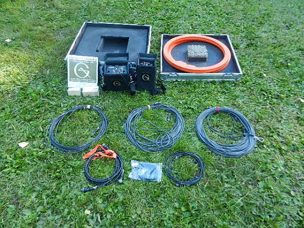
Typical EM34-3 Packing List
1 x EM34-3 Receiver and 2 x Receiver Cables
1 x Transmitter and 2 x Transmitter Cables
1 x Set of 3 Reference Cables (10m, 20m, and 40m)
2 x Cable (EM 34 console to Allegro Data Logger)
1 x Set of User Manuals
1 x Shipping Case (32 x 32 x 14, 105 lbs)
User Manuals
EM34-4 Specifications
MEASURED QUANTITIES: Apparent conductivity in millisiemens per metre (mS/m)
PRIMARY FIELD SOURCE: Self-contained dipole transmitter
SENSOR: Self-contained dipole receiver
REFERENCE CABLE: Lightweight, 2 wire shielded cable
INTERCOIL SPACINGS & OPERATING FREQUENCY:
10 m at 6.4 kHz
20 m at 1.6 kHz
40 m at 0.4 kHz
POWER SUPPLY:
Transmitter: 8 disposable or rechargeable “D” cells
Receiver: 8 disposable or rechargeable “C” cells
CONDUCTIVITY RANGES: 10, 100, 1k mS/m
MEASUREMENT RESOLUTION: +/- 0.1% of full scale
MEASUREMENT ACCURACY: +/- 5% at 20 mS/m
NOISE LEVELS: Conductivity: 0.2 mS/m (can be greater in regions of high power line interference)
DIMENSIONS:
Rx Console: 19×13.5×26 cm
Tx Console: 15.5x8x26 cm
Rx & Tx Coil: 63 cm diameter
EM34-3XL Tx Coil: 100 cm
Case: 27.5x75x75 cm
INSTRUMENT WEIGHT: 20.5 kg; XL: 26.5 kg